PSCAD software latest version V4.6 function introduction
This article is translated by China Science Software Network
PSCAD software V4.6 new features introduced
New and expanded features
1. Grid Interface (ENI): Developed a way to make subnets electrically connected to each Other in a single project and as a complete network. This interface essentially provides a way to break down large power networks into subnets, and then connect them to each other to run each process individually or a single processor core. Communication is done via TCP/IP sockets. The transport segment component was changed to improve this interface, and the communication interface between EMTDC and PSCAD was also changed.

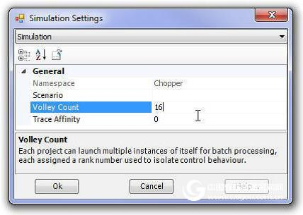
1. Volley Launch/Root Control: Based on a single PSCAD case project, Volley can perform multiple EMTDC simulations in parallel (up to 64). Set up a volley, this simulation must first be added to the simulation set. Once added, you can simply call the Simulation Options dialog and adjust the Volley Count option. For example, if you want to start 7 simulations in a project, you need to set the Volley number to 7. The next time you start the simulation set, there will be 7 instances of parallel simulation, taking advantage of all available processors.
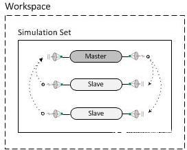
The Root Control Interface (RCI) was first introduced in an upgraded version of PSCAD V4.5. The root control allows one root or main project to control multiple subprojects, but both the main project and the subproject must be of the same simulation set. The reason for the development of RCI is to support parameter scanning, optimization estimation, and multi-running research.
Like the simulation set, RCI is an inherent part of the workspace that supports internal project communication in a single simulation set. This is achieved by using already defined radio transmitter and receiver components, which are included as extensions in the V4.5 version to provide space for language naming in other countries. This indicator link collects its value from external sources, supporting a more complex approach to multiple operations.
3. License: The first version of PSCAD is licensed by binding to the target machine hardware. However, starting from the earliest windows platform, this method is no longer applicable, so a new system that can install the license manager through the electronic dog or on the user server is introduced. The license manager model is basically a distributed authorization model, where we let customers follow the license to the web server. This form of licensing leads to the next generation licensing system, which provides a renewable energy licensing strategy to manage tracking license usage servers.
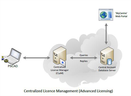
In addition to the original intranet-based licensing form, PSCAD also supports cloud-based certificate licensing, provided the client requires a license manager. The certificate license provides a time-limited license from MyCentre, an Internet-based user portal. This allows users to work offline, leaving the network without having to connect to their license manager, license file, or electronic dog. Certificate licensing is more flexible, and it offers a variety of new licensing concepts, such as licensing for personal use.
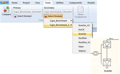
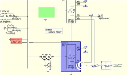
4 Comparator Tools: The Schematic Comparator tool provides a quick and easy visual distinction between model component definitions.
Select two sources for comparison (from the Tools tab of the feature navigation bar), and the user can click on the "Compare" button to make a comparison of the two definitions.
The user can see the visual difference display between the two modules. The results table will give the user a textual description of the difference and the different values ​​found. In addition, component differences are indicated by colored highlight boxes in the main source schematic.
5. Parameter Grid Pane: The Component Parameters Grid panel provides a convenient way to display the parameters defined for components and models in all instances. More importantly, it can modify multiple parameter values ​​in multiple component instances simultaneously.

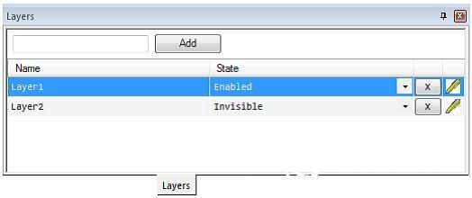
6. Layer pane: The layer pane is the schematic painting layer function interface. The paint layer provides the ability to effectively enable or disable components on the canvas, or to switch the visibility of any object on the canvas.
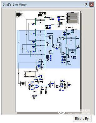
7. Bird's Eye Navigation Pane: The Bird's Eye View Navigation Pane allows you to view the entire schematic and drawing canvas, or use a blue box to identify the file being viewed. This tool is an important part of the PSCAD navigation tool and can be easily scaled and navigated. This pane is especially useful when working with very large projects (#1252).
8. Support for Intel Fortran 15: Intel® Visual Fortran Compiler for Windows 14 or 15 version support has been added.
9. GFortranv 4.6.2 upgrade: This PSCAD comes with a free compiler that has been upgraded from v4.2.1 to v4.6.2. This upgrade solves many vulnerabilities in the old version.
10. Load a project or workspace by dragging and dropping: The project or workstation can now be loaded into the application environment by dragging and dropping. Simply select a project or workspace file (from the Windows File Explorer) and drag it to the workspace window and release the mouse button to load the file (#3184).
11. Black Box Module Hierarchy Support: The Black Box algorithm now supports the entire module hierarchy of Black Box. The same rules apply to a single black box model (such as no output channels and runtime components, etc.). Black Box collects all unique module definitions and generates source files (*.f) and compiled object files (*.obj). This further binds all object files to a static library file (*.lib) (#4587).
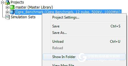
12. Folder display: Project and workspace files can now be displayed directly in each folder. Just right click on the loading project or workspace and select the folder display. This can be used to call the Windows File Explorer and set the folder where the corresponding file is located (#4557).
13. Horizontal scrolling with Shift and the mouse wheel: The user can now pan the schematic canvas by holding down the Shift key and scrolling the mouse wheel (#2636).
14. Multiple Run Jumps: Wrong instructions can take a lot of time when dealing with large simulations and multiple runtime scenarios. In the past we have been asking for a 'dry' simulation that allows the user to quickly check to make sure that each running configuration is valid.
Unfortunately, there is no way to just run the part and then jump to the next sequence to run.
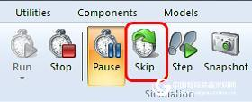
We added a new 'Skip' button to the menu bar that will send a message to EMTDC indicating that it jumps to the end of the run and starts running the next one. In the simulated case set and master/slave batch configuration (including volley), the entire coordinated run will jump to the next iteration (#404).
15. Runtime "Slow Motion": When we're always working on fast and large simulations, sometimes small simulations are also important. Especially when trying to prove or study an event that occurs in a short period of time. If the simulation is small, the process is very fast, so it is difficult to see what happens. What we need to do is actually slow down the process of the whole process, that is, the slow-motion effect, just like we manually slow down the time step. This is slow by using
Speed ​​reduction control and slow slip control have been implemented.
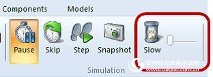
For demonstration and teaching purposes, the user can control how quickly the process is executed. The toggle button controls the speed and the slide control can be delayed from 1ms to 10ms (#1527).
16. Single-spaced fonts in the information table: In order to maintain compatibility with messages from the Fortran compiler, the font of the message table is changed to a single-spaced font. This will help those messages that rely on a single-spaced font layout to produce any meaning (#2636).
17. Local Complex Declaration: Local Complex Variables can now be specified in the component definition script (#2099)
18. Work progress bar: The progress bar has been added to the workspace project and simulation tree. When running a standalone project, the progress bar will appear directly after the project name (if enabled), showing its runtime completion percentage.
The progress bar option is disabled by default. The option of the Show quick run progress bar can be called up via the application options dialog of the workspace category.

If you run a root control simulation (such as master or slave configuration), the progress bar will appear near the simulation task of the simulation tree.

19. Manual and Point Selection Tool: Two new selection tools, manual and selection tools have been added to the toolbar.
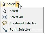
The manual selector supports a circle that contains a set of components in hand animation, similar to 'lasso'.
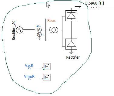
The other is the point selector, which contains a collection of polygons or points:
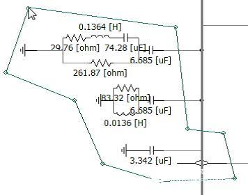
20. Workspace Integration: A new feature has been added to help integrate and organize workspaces. Workspaces are sometimes difficult to work with, and may contain several projects and link to source code or binaries. Projects and related files are scattered across local folders, making it very cumbersome to move workspaces from one computer to another. Workspace integration mitigates this problem by allowing users to integrate, organize, and reset all relevant file paths with a single mouse click.

The workspace integrator moves all projects to a folder structure similar to the following:

The component library and case project are divided into personal folders and related folders, which are all saved in their own resource folder.
Any case project in the Workspace Integrator can be created and run immediately without additional modifications. If transferred via email, the entire folder structure can be easily compressed using the default compression tool.
22. 64-bit EMTDC: The new PSCAD includes a new 64-bit EMTDC version. It should be noted that 64-bit EMTDC can only be used with Intel® Visual Fortran Compiler for Windows 15 or higher and 64-bit PSCAD.
22. Project Auto Backup and Repair: PSCAD will save a backup file of the workspace and all loaded files. This document is updated every 30 seconds and the exited application is deleted. If the application crashes, the backup file will be detected and restarted, and the user will be asked if they want to restore the backup file.
Defect repair
1. Subsystem Demolition Options: Subsystem Demolition Options (mixed and combined non-switched networks) have been removed from the Project Settings dialog because they have become obsolete since the V4.3 release. When the subsystem enables the split function, EMTDC default memory usage is optimized (#4175).

2. Transmission Line Circuit Overlay: The Transmission Line Configuration component adds a new parameter that allows the user to overlay multiple t-line circuits into the same three-phase bus. The parameter can only be enabled if the line is 6, 9 or 12 conductors and the line is in direct connection mode. When the selected parameters are superimposed, you can connect a 6, 9 or 12 phase line to a separate three-phase bus (#4639).

In essence, this feature eliminates the need for three-phase to six-phase circuit breaker components, which tends to make the circuit more cluttered.


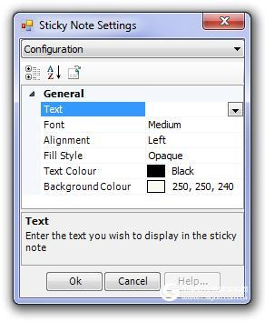
3. New Post-It Box Dialog: The tabbed dialog has changed the current list format to be consistent with other components. The new dialog provides the same functionality as the original, including a color palette for the font and background (#4762).
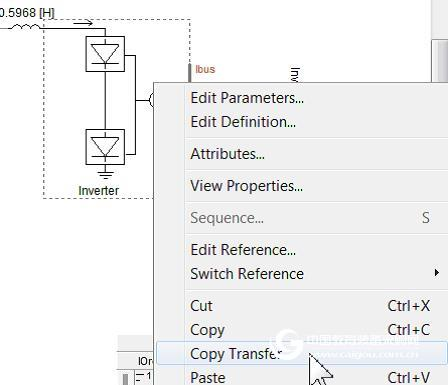
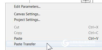
4. Copy Transfer: This function is based on the copy slave function, which was added in v4.3. A replication slave is a simple definition copy of the module's hierarchy, including all related modules. There are two main drawbacks to copying a transport's predecessor: The instance information (ie, the parameter value) of the topmost module is included in the copy and the module hierarchy is automatically relinked when pasted, even if some or all of the definitions need to be renamed. In addition to these, copy transport also provides the convenience of copying directly from a component instance instead of using a definition tree (#3289).
5. File path relative to the project folder: As of v4.6, the relative file path is read as a related project folder instead of a temporary folder. When loading a legacy project, PSCAD will attempt to determine the correct location of the file. If the My Projects application option is specified, it will handle the relative path even if it is from a folder that uses environment variables (# 5249).
6. Search History: PSCAD can search history (#4926/#4925) in the search area of ​​the search panel.
7. File path supports wildcards: The file path uses the wildcard function (ex. *.c, x.*, *.*, abc*def.s) has been added to the Additional Source files (*.f, *.for, * .f90, *.c, *.cpp), Additional Library (*.lib) and Object (*.obj/*.o) Files in the project settings file. This allows the user to specify a folder to find the source without having to specify an exact file name (# 464).
8. Suspend a single project in the simulation set: If the project's run configuration is set to standalone, the project can now be aborted separately. It is not possible to abort a project that is set to be a primary or dependent library (#4193).
9. View license details: View license details have been simplified and can be viewed via the drop-down list in the upper right corner of the function menu bar (#5574).

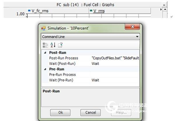
10. International Simulation Setup Command Line Options: Custom commands can now be executed before the simulation setup runs or when the simulation setup run is to be performed immediately. It allows users to push and pull information and possibly analyze data between data sets. For example, a batch file can copy or move the EMTDC output file to another folder (#5453) before the next simulation set begins.
The drawing panel adds $(instance): in order to display the model name and the number of instances in the drawing panel, a new directive has been added. For example, $(INSTANCE) : $(GROUP) : The graphical results are as follows:
Bug fix
Added "Delete" item to multiple partial popup menus (#4349).
2. When the GFortran v4.2.1 compiler (provided by PSCAD v4.3 - v4.5) is used in multiple runtime environments, the vulnerability inherent in the compiler itself causes memory consumption and is not properly addressed. This will cause a crash after multiple runs. This issue has been fixed by providing the latest GFortran v4.6.2 (# 3748).
3. The GFortran v4.2 release (provided by PSCAD v4.3 - v4.5) vulnerabilities including snapshots have been remediated by the latest GFortran v4.6.2. When attempting to run a simulation from a generated snapshot file, this run will fail if using GFortran v4.2.1 and Windows XP. This issue cannot be resolved unless you upgrade to the latest GFortran version (#3388).
4. "Relative Path" is displayed under the "General" tab of the Project Settings dialog box and is displayed in the corresponding workspace (#4799).
5. Enter '# runs' in the menu bar 'Project' to verify the validity of the data (#3883).
6. When the menu area view is zoomed out, the ribbon text box and drop-down list function is normal (#4411).
7. New optimization techniques have been used to speed up the compilation of large projects (#4509).
8. When the graphic object property of the function menu bar changes, the graphic component is no longer left in the canvas (#4753).
9. The application option removes the MATLAB library path display (#3194).
10. When one of them is modified (such as ribbon, project settings, etc.), all episode-level input files remain synchronized (# 3675).
11. When navigating, the node count search results point to the correct module instance (#4951).
12. The Manual Refresh option has been added to the Schematic/Artwork pane (#4392).
13. When searching for the current project internal namespace module example, the search function is normal. Previously, internal namespace modules were ignored because their definitions were not saved in the local current project (#5164).
14. Multiple library projects (*.pslx) have the same namespace and will not be loaded into a separate workspace. All namespaces in all projects must now be unique (#5321/#5336/#5389).
15. Graphics Editor The canvas size is now saved as part of the component definition (eg page size is now saved with the project) (#5257).
16. If the file cannot be found, a reference file path (# 5412) is displayed in the file reference component in the created information.
17. The ITXRX array is now public, and the NTXRX pointer is now incremented to generate the correct code, which is used to save the project (#5455) when using the root control.
18. PSCAD now handles custom component script snippets and replaces illegal characters with a downline (such as ' and '). This ensures that the component's script code conforms to the Xml standard (#5588).
19. Minor issues regarding misstatement of case mismatch check information in t-lines and cables have been corrected (#5481).
20. Ctrl + left mouse button drag to copy a post-it is now functional (# 5576).
21. The grid diagram of the y-axis in the overlay is no longer reset when the simulation starts. Previously, even with manual scaling, PSCAD was the best fit for the grid (#5586).
22. Transmission lines and cables are located in one module and their definitions are stored in a library project, but being instantiated in the case project will no longer result in a mapping file error (#5592).
23. Enter the parameter value ".xx" with no zero before it will now be automatically changed to "0.xx(#5492).
24. Grammar usage no longer exceeds its text cache limit when reading. This can cause a crash in some cases (#5582).
25. When a user defines a naming after the main library definition, PSCAD no longer crashes. The project is compiled and the interfering components are illegally added to the internal vector list (#5409).
26. Based on a single license, multiple instances of the PSCAD application can now be opened simultaneously in the same workspace. This feature is only available when using a license (#1686).
27. Surge Generator (CIGRÉ, IEC or IEEE Standard): The surge waveform generated by this component, commonly used for lightning protection studies, in accordance with CIGRÉ, IEC or IEEE standards.
Main library
New model, enhancements and bug fixes
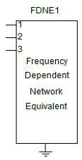
1. Frequency-Dependent Network Equivalent Model (FDNE): This component can be used to simulate the frequency domain characteristics of a circuit. In the power system, the FDNE model may represent a reduced-order network equivalent, a high-frequency transformer model, and a short transmission line (#2348).
2. Frequency-Dependent Transfer Function Model (FDTF): This component emulates a multi-port transfer function that is used as part of any control system. The component I transfer function is based on the state space and is implemented using the ABCD parameter construct.

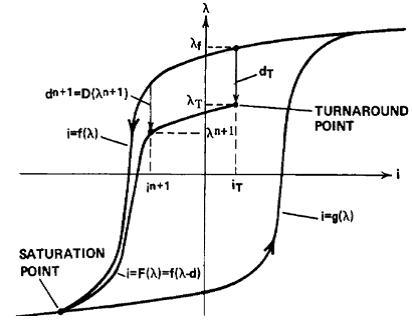
3. Transformer hysteresis: The core hysteresis algorithm has been added to all traditional transformer assemblies. The algorithm includes two unique hysteresis modeling techniques: the basic (loop width) model and the Jiles-Atherton model. Of course each model configuration is different; the basic model is two of the simpler models (#2352/5293).
4. Programmable Breakpoint Component: The "Pause" and "Stop" components have been added to the main library to provide pause and stop emulation based on the emulation signal. When an integer input operation is performed, these components will pause or stop the simulation while detecting a rising edge. This effectively provides the "Run" or "Breakpoint" feature (# 1645 / # 1645).

5. Battery Model: Based on the electrochemical and list data battery model, the battery model has been added to the main library. The battery is modeled using a general method using an ideal controllable voltage source control and series resistor (#3481).

6. 12-Channel decoder enhanced to N-Channel: Previously, the 12-channel decoder was of course a limited 12 output channels. This component has been modified to now have an infinite (eg N-dimensional) output channel (#4207, #4207).

7. Permanent magnet motor multi-mass interface: Interfaces from multi-mass components have been added to permanent magnet motors (#4538).
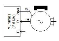
8. Machine Speed ​​/ Mechanical Torque Input: DC and permanent magnet motors are now configured to accept speed or mechanical torque inputs, similar to the Synchronizer and Induction functions (#3625).
9. Hard Limit Component External Input: The external limit connection has been added to the hard limit component (#2789, #2789).

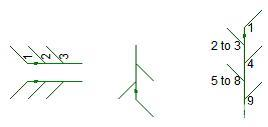
10. The data merge component now supports array signals: in addition to scalars, array signals (#4531) can now be merged.
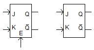
11. The trigger adds a lock mode operation: The trigger component now supports lock mode operation and operates on an optional start signal (#2821/4532).
12. Statistical breaker model: The statistical breaker assembly has been added to the main library. The assembly is used in a statistically distributed manner for unipolar operation of a three-phase circuit breaker (#3586).

13. Dynamic Data Interface Component: This component outputs a signal (scalar or array) based on the connection of the input starting index. The dimensions of the output are defined in the parameters section. If the start index selection and output dimensions refer to the external factors of the input array, the component will warn and output zero (or .FALSE) depending on the data type (#4594).

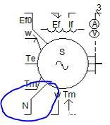
14. Synchronous motor neutral point connection: The synchronous motor has been extended to the connection point that allows the user to access the neutral point. Enable additional connection N, which is controlled by a new component input parameter (#2841).
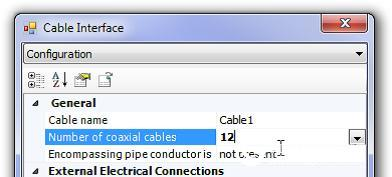
15. Maximum number of cables increased: The maximum number of cables per line has been increased from 8 to 12. This change affects the cable interface component and the line constant program (LCP) (# 5014).
16. External Connection Resistor for Cable Interface: A cable interface component option is provided that allows the user to automatically connect an external resistor to the ground (#5018).

17. Order: This component outputs the simulation order as part of the volley startup. Note that the order of the non-volley simulation is zero. Combined with a lookup table method, such as an XY transfer function or an XY table, this component can be used to simulate different data runs into a volley for simulation (#5131).

18. Change multiple run file naming formats: If this simulation order is 0, you can use the naming behavior of the current file to name it. However, if the order is not zero, the output file name is now formatted as mrunout_##.out, where ## means 2 orders (#5122).
19. Single-phase, three-winding UMEC transformer model (substitute): This new component ((umec-xfmr-3w2) replaces the original single-phase, three-winding UMEC transformer model (umec-xfmr-3w). In this new In the component, the winding leakage inductance and copper loss can be specified separately, rather than evenly distributing the total value in all windings (#2746).

20. Multimeter: The measured rms current has been added to the multimeter assembly (#5169).
21. MOD and MODULO components: MOD and MODULO components have been added to the CSMF part of the main library (# 3127 / # 3127).

22. The output channel can assume the signal name: a new parameter is added to the output channel component, allowing the channel to assume the name of the signal it is connected to. If this parameter is set to Yes, the name of the output channel will be replaced by its corresponding signal name when the next project is compiled. Note that the output channel name will also be changed each time the signal name is changed. Also note that if this parameter is enabled, the original output channel name will be lost (#2792).

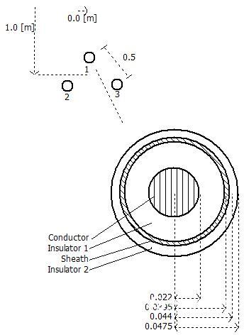
23. Simplified underground cable: This cable assembly is used to simulate an underground cable system. It simplifies the cable system cross-section structure, simplifies data entry by utilizing data replication, and provides a more conformable cable data sheet. This component can be easily adjusted to represent the typical system configuration as follows:
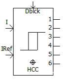
24. Hysteresis Current Control PWM Generator: Based on hysteresis current control, this component generates a PWM signal (#5300).
25. Maximum/Minimum Array Value and Position: The Maximum/Minimum Array Value and Position component allows the circuit designer to find the minimum or maximum element value and position in the array signal.

26. Array dot product: This component is used for the dot product of the two arrays. For example, you can use the dot product of three-phase voltage and current to measure instantaneous power (#5302/#5313).

27. Surge Generator (CIGRÉ, IEC or IEEE Standard): This component generates surge waveforms, commonly used for lightning protection studies, in accordance with CIGRÉ, IEC or IEEE standards (#5652).

28. Update Multi-Mass components: This updated component configures the location of the generator and exciter. This component before the update makes the generator and exciter must be at the end of the spinning mass (#5639).
Bug fix
1. When the permanent magnet is scanned, the Frequency Scanner component will give the correct result (#4459).
2. The first data point in the File Reader component can be specified as arbitrary, not TIMEZERO(#4395).
3. The parameter options in the Y, Z manual input components are consistent with the category name (#4938).
4. According to the upgraded IEEE Standard 421.5 (1992), the PSS2B stabilizer component now accepts the 5th order (#1921).
5. The default name of the new cable interface component created by the Component Wizard is 'Cable_1' (#5030).
6. When the voltage of the node, that is, the frequency measurement, is lower than the set rated voltage, the Frequency and Incremental Phase Measurement component can correctly measure the frequency (#4160).
7. Solved the problem of unused variables in the Voltage Source Model 1 component (called Initial Source Magnitude parameter input) (#5053).
8. If you use multiple run components and settings to the output monitor in the main library project, the multi-run component will give an error message. If allowed, the output generated from the project is synchronized and an incorrect information output file (#5138) is generated.
9. When using multiple running components in a dependent project, an error message (#5139) is given.
10. When the project is enabled, EMTDC will send a message to the message table with the existing frequency scanner component running (#4922).
11. The hydraulic regulator 2 main library component (hy_gov) responds correctly to the pulldown settings (#5167).
12. When using non-uniform speeds, the multi-quality model is properly initialized (#5215).
13. Check the lens21 and apple 21 components to determine if the distance between the two circles (including the lens and apple shapes) is too far away. When using the polar format, it works fine (#5282).
14. The apple21 component will not report an error when the variable is replaced (#5278).
15. The problem that occurred in the fixed_load component has been corrected when used in a constant power configuration (#5277).
16. EMTDC will not fail when compiling with GFortran (#5312).
17. A regular expression check has been added to the RTP / COMTRADE component to prohibit the entry of names greater than 8 characters. A warning warning message (#2705) when the name is adjusted to 8.3 format has also been added.
18. The ctype filter component in the main component library has parameters and ports with the same name ('C'), which will result in an incorrect Fortran script (#5435).
19. The simulation crashes (#5176) when the multiple run output file name in the multiple run component is empty.
20. When there are no random variables in any of the output files, the multi-running component no longer records the incorrect original value (#5258).
21. The cancellation time constant for the frequency/phase measurement component is detected and guaranteed to be greater than 1 millisecond. The phase output is less unstable (#5486).
22. Corrected a no load losses issue in the 3-phase, 2-winding transformer component (#5715).
22. Corrected the no-load loss problem in the three-phase, two-winding transformer assembly (#5715).
23. Configuring a single time step delay issue has been fixed. It turns out that this component will generate 2 time step delays (#5737).
EMTDC
Functional extension and defect repair
Output file format: The EMTDC output file naming convention has been modified to include simulation rankings. The format is changed from _r########(#).out to _r##_m#####_##(#).out, r is the order, and m is the number of multiple runs ( #5122/#5135).
2. EMTDC Information Importance Level: EMTDC can submit information and return to the PSCAD pre-set importance level. Levels include information, warnings, and errors. This is achieved by a new method called EMTDC_MESSAGE, which replaces EMTDC_WARN and EP_ERROR (#5324).
3. Harmonic Impedance Interface for Custom Components: A new generalized harmonic impedance interface solution has been added. The custom component is now included in the frequency sweep (#3489).
4. Upgrade pole/residue removal algorithm: The new two-sided integration method can be used to remove frequency-dependent, large pole-residue ratios of curve fitting results.
Bug fix
1. The band limit detection algorithm works normally (#3036/#4899).
2. EMTDC allows the actual plot to be processed using PSCAD (#4119).
3. Spelling and grammar errors are corrected in the EMTDC source message (#5377).
4. If the transmission route duration is less than 80% of the simulation time step, EMTDC will stop the simulation. When the original transmission route duration is less than 50%, EMTDC will stop the simulation (#5085).
LCP
New features, extensions and bug fixes:
1. The line constant program now supports multiple points of 12 cables, including concentric (#4917).
2. The minimum value of the two coaxial cables in the pipe has been removed. Users can simulate a pipe type cable, including a single, coaxial cable or an empty pipe (without internal cable) (#4856).
3. Support multi-pipe type cable (#4857) in the same line corridor.
4. The traditional functional approach used by the DC correction algorithm has been replaced by a new approach. The new method is simple and powerful and does not require the use of constrained optimization methods. The new method also solves the link problem (#4860) that occurs when using the previous method.
Bug fix
1. LCP and EMTDC are added to the inspection function to ensure the validity of the calculation time (#4777).
2. The equivalent cross-section component generator in a large cable system functions properly. Fixed a formatting error in the script (#5015).
3. When the distance between two transmission lines or cables is very large, the mutual impedance calculation no longer fails (#4990).
4. If a negative or invalid delay time is calculated, the line constant program warns the user (#4328).
5. The line constant program verifies the illegal, zero-length transmission segment (#5434).
6. The long-line correction algorithm provides harmonic impedance (#5221) with the correct hyperbolic function solution under certain parameters.
7. The line constant program will determine the zero DC resistance and stop further processing. Previously, when a very large error was output, the process did not stop (#5546).
8. The passive detection algorithm now displays the frequency range and the corresponding maximum negative eigenvalue (#5556).
9. When the last layer in the pipe is a wire, the line constant program provides the correct capacitance value (#5557).
10. The line constant program detects and ensures that the input ground resistance is not zero. Zero ground resistivity can cause EMTDC to crash (#5408/5437).
11. The line constant program checks for non-physical, negative, and long-line corrected inductor and capacitor values. If you find a problem, there will be an error alert #5664).
12. The DC correction algorithm works fine when simulating overhead cables (#5622).
Triangle bending fence is an economical version of the panel system, constructed from a Welded Wire Fence with longitudinal profiles that forms a rigid fence.Due to its simple structure ,easy installation and nice appearance,more and more customers regard this product as the preferred common protective fence.Triangle bending fence is one of the most important ways to keep your home safe and secured from all forms of attacks by armed robbers and so on.with it's smooth surface,not fading,not cracking.For garden fences, decorative fences, security fences, expressway, railway, Barbed Wire fences, Chain Link Fence, expanded metal fences, etc.

Triangle Bending Fence,Triangle Bending Bend Fence,Triangle Bending Fence Wire Mesh
Hebei Giant Metal Technology Co., Ltd. , https://www.hebeigiantmetal.com